hide long namesshow long names
hide short namesshow short names
Integer type:  int32  int64  nag_int  show int32  show int32  show int64  show int64  show nag_int  show nag_int

PDF version (NAG web site, 64-bit version, 64-bit version)
Chapter Contents
Chapter Introduction
NAG Toolbox

NAG Toolbox: nag_mesh_2d_gen_front (d06ac)

 Contents

    1  Purpose
    2  Syntax
    7  Accuracy
    9  Example

Purpose

nag_mesh_2d_gen_front (d06ac) generates a triangular mesh of a closed polygonal region in 2, given a mesh of its boundary. It uses an Advancing Front process, based on an incremental method.

Syntax

[nv, nelt, coor, conn, ifail] = d06ac(nvb, edge, coor, weight, itrace, 'nvint', nvint, 'nvmax', nvmax, 'nedge', nedge)
[nv, nelt, coor, conn, ifail] = nag_mesh_2d_gen_front(nvb, edge, coor, weight, itrace, 'nvint', nvint, 'nvmax', nvmax, 'nedge', nedge)

Description

nag_mesh_2d_gen_front (d06ac) generates the set of interior vertices using an Advancing Front process, based on an incremental method. It allows you to specify a number of fixed interior mesh vertices together with weights which allow concentration of the mesh in their neighbourhood. For more details about the triangulation method, consult the D06 Chapter Introduction as well as George and Borouchaki (1998).
This function is derived from material in the MODULEF package from INRIA (Institut National de Recherche en Informatique et Automatique).

References

George P L and Borouchaki H (1998) Delaunay Triangulation and Meshing: Application to Finite Elements Editions HERMES, Paris

Parameters

Compulsory Input Parameters

1:     nvb int64int32nag_int scalar
The number of vertices in the input boundary mesh.
Constraint: nvb3.
2:     edge3nedge int64int32nag_int array
The specification of the boundary edges. edge1j and edge2j contain the vertex numbers of the two end points of the jth boundary edge. edge3j is a user-supplied tag for the jth boundary edge and is not used by nag_mesh_2d_gen_front (d06ac).
Constraint: 1edgeijnvb and edge1jedge2j, for i=1,2 and j=1,2,,nedge.
3:     coor2nvmax – double array
coor1i contains the x coordinate of the ith input boundary mesh vertex, for i=1,2,,nvb. coor1i contains the x coordinate of the i-nvbth fixed interior vertex, for i=nvb+1,,nvb+nvint. For boundary and interior vertices, coor2i contains the corresponding y coordinate, for i=1,2,,nvb+nvint.
4:     weight: – double array
The dimension of the array weight must be at least max1,nvint
The weight of fixed interior vertices. It is the diameter of triangles (length of the longer edge) created around each of the given interior vertices.
Constraint: if nvint>0, weighti>0.0, for i=1,2,,nvint.
5:     itrace int64int32nag_int scalar
The level of trace information required from nag_mesh_2d_gen_front (d06ac).
itrace0
No output is generated.
itrace1
Output from the meshing solver is printed on the current advisory message unit (see nag_file_set_unit_advisory (x04ab)). This output contains details of the vertices and triangles generated by the process.
You are advised to set itrace=0, unless you are experienced with finite element mesh generation.

Optional Input Parameters

1:     nvint int64int32nag_int scalar
Default: the dimension of the array weight.
The number of fixed interior mesh vertices to which a weight will be applied.
Constraint: nvint0.
2:     nvmax int64int32nag_int scalar
Default: the dimension of the array coor.
The maximum number of vertices in the mesh to be generated.
Constraint: nvmaxnvb+nvint.
3:     nedge int64int32nag_int scalar
Default: the dimension of the array edge.
The number of boundary edges in the input mesh.
Constraint: nedge1.

Output Parameters

1:     nv int64int32nag_int scalar
The total number of vertices in the output mesh (including both boundary and interior vertices). If nvb+nvint=nvmax, no interior vertices will be generated and nv=nvmax.
2:     nelt int64int32nag_int scalar
The number of triangular elements in the mesh.
3:     coor2nvmax – double array
coor1i will contain the x coordinate of the i-nvb-nvintth generated interior mesh vertex, for i=nvb+nvint+1,,nv; while coor2i will contain the corresponding y coordinate. The remaining elements are unchanged.
4:     conn32×nvmax+5 int64int32nag_int array
The connectivity of the mesh between triangles and vertices. For each triangle j, connij gives the indices of its three vertices (in anticlockwise order), for i=1,2,3 and j=1,2,,nelt.
5:     ifail int64int32nag_int scalar
ifail=0 unless the function detects an error (see Error Indicators and Warnings).

Error Indicators and Warnings

Errors or warnings detected by the function:
   ifail=1
On entry,nvb<3,
ornvint<0,
ornvb+nvint>nvmax,
ornedge<1,
oredgeij<1 or edgeij>nvb, for some i=1,2 and j=1,2,,nedge,
oredge1j=edge2j, for some j=1,2,,nedge,
orif nvint>0, weighti0.0, for some i=1,2,,nvint;
orlrwork<12×nvmax+30015,
orliwork<8×nedge+53×nvmax+2×nvb+10078.
   ifail=2
An error has occurred during the generation of the interior mesh. Check the definition of the boundary (arguments coor and edge) as well as the orientation of the boundary (especially in the case of a multiple connected component boundary). Setting itrace>0 may provide more details.
   ifail=-99
An unexpected error has been triggered by this routine. Please contact NAG.
   ifail=-399
Your licence key may have expired or may not have been installed correctly.
   ifail=-999
Dynamic memory allocation failed.

Accuracy

Not applicable.

Further Comments

The position of the internal vertices is a function position of the vertices on the given boundary. A fine mesh on the boundary results in a fine mesh in the interior. During the process vertices are generated on edges of the mesh Ti to obtain the mesh Ti+1 in the general incremental method (consult the D06 Chapter Introduction or George and Borouchaki (1998)).
You are advised to take care to set the boundary inputs properly, especially for a boundary with multiply connected components. The orientation of the interior boundaries should be in clockwise order and opposite to that of the exterior boundary. If the boundary has only one connected component, its orientation should be anticlockwise.

Example

In this example, a geometry with two holes (two wings inside an exterior circle) is meshed using a Delaunay–Voronoi method. The exterior circle is centred at the point 1.5,0.0 with a radius 4.5, the first wing begins at the origin and it is normalized, finally the last wing is also normalized and begins at the point 0.8,-0.3. To be able to carry out some realistic computation on that geometry, some interior points have been introduced to have a finer mesh in the wake of those airfoils.
The boundary mesh has 120 vertices and 120 edges. Note that the particular mesh generated could be sensitive to the machine precision and therefore may differ from one implementation to another.
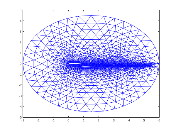
function d06ac_example


fprintf('d06ac example results\n\n');

% The characteristic points of the boundary mesh
coorch = [0, 1, -3, 6,  0.8,  1.8, 1.5,  1.5;
          0, 0,  0, 0, -0.3, -0.3, 4.5, -4.5];
coorus = zeros(2,100);
% The lines of the boundary mesh
blines = [int64(21), 21, 11, 11, 21, 21, 11, 11;
                   2,   1,  3,  4,  6,  5,  7,  8;
                   1,   2,  8,  7,  5,  6,  3,  4;
                   1,   2,  3,  3,  4,  5,  3,  3];
rate = ones(8,1);

% The number of connected components to the boundary
ncomp = int64(3);
% Number and direction of lines per contour
nlcomp = [int64(-2), 4, -2];
% List of line numbers
lcomp = [int64(1), 2, 3, 8, 4, 7, 5, 6];

user = struct('x0', 1.5, 'y0', 0, 'radius', 4.5, 'x1', 0.8, 'y1', -0.3);

nvmax = int64(2000);
nedmx = int64(200);
itrace = int64(0);


[nvb, coor, nedge, edge, user, ifail] = ...
d06ba( ...
       coorch, blines, @fbnd, coorus, rate, nlcomp, lcomp, nvmax, ...
       nedmx, itrace, 'user', user);
fprintf('\nBoundary mesh characteristics:\n');
fprintf('  nvb   = %d\n', nvb);
fprintf('  nedge = %d\n', nedge);

% Generation of interior vertices for the wake of the first naca
nvint  = 40;
nvint2 = 20;
dnvint = 5/(nvint2+1);
weight = ones(nvint,1)/nvint2;
for i=1:nvint2
  coor(1, nvb+i) = 1+i*dnvint;
end
% ... for the wake of the second naca
for i = nvint2+1:nvint
  coor(1, double(nvb)+i) = 1.8 + (i-nvint2)*dnvint;
  coor(2, double(nvb)+i) = -0.3;
end

% Call the 2D advancing front mesh generator.  Note only pass relevant
% portion of edge
[nv, nelt, coor, conn, ifail] = ...
d06ac( ...
       nvb, edge(:,1:nedge), coor, weight, itrace);

fprintf('\nComplete mesh characteristics:\n');
fprintf('  nv    = %d\n', nv);
fprintf('  nelt  = %d\n', nelt);

% Plot mesh
fig1 = figure;
triplot(transpose(double(conn(:,1:nelt))), coor(1,:), coor(2,:));


function [result, user] = fbnd(i, x, y, user)

  result = 0;
  c = 1.008930411365;
  p4 = @(x) 0.6*( 0.2969*sqrt(c*x) - 0.126*c*x - 0.3516*(c*x)^2 + ...
		  0.2843*(c*x)^3 - 0.1015*(c*x)^4 ); 
  if (i==1)
    % upper naca0012 wing beginning at the origin
    result = p4(x) -c*y;
  elseif (i==2)
    % lower naca0012 wing beginning at the origin
    result = p4(x) + c*y;
  elseif (i==3)
    result = (x-user.x0)^2 + (y-user.y0)^2 - user.radius^2;
  elseif (i==4)
    % upper naca0012 wing beginning at (user.x1;user.y1)
    result = p4(x-user.x1) - c*(y-user.y1);
  elseif (i==5)
    % lower naca0012 wing beginning at (user.x1;user.y1)
    result = p4(x-user.x1) + c*(y-user.y1);
  end
d06ac example results


Boundary mesh characteristics:
  nvb   = 120
  nedge = 120

Complete mesh characteristics:
  nv    = 1894
  nelt  = 3664
d06ac_fig1.png

PDF version (NAG web site, 64-bit version, 64-bit version)
Chapter Contents
Chapter Introduction
NAG Toolbox

© The Numerical Algorithms Group Ltd, Oxford, UK. 2009–2015