| (i) | if the th edge is part of the partition interface, then will contain the value where and are the tags for the same edge of the first and the second mesh respectively; |
| (ii) | otherwise, will contain the same tag as the corresponding edge belonging to the first and/or the second input mesh. |
| On entry, | , |
| or | , |
| or | , |
| or | , |
| or | or for some and , |
| or | for some , |
| or | or for some and , |
| or | or or for some , |
| or | , |
| or | , |
| or | , |
| or | or for some and , |
| or | for some , |
| or | or for some and , |
| or | or or for some , |
| or | . |
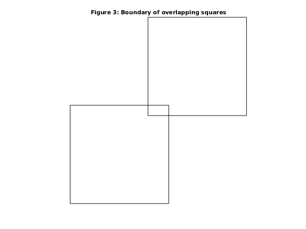
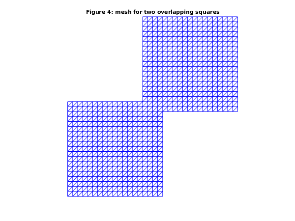
| (a) | overlapping meshes (, ), |
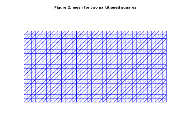
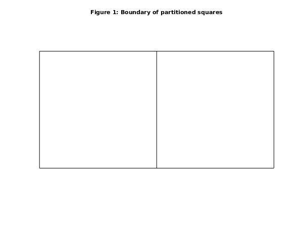
| (b) | partitioned meshes (, ). |
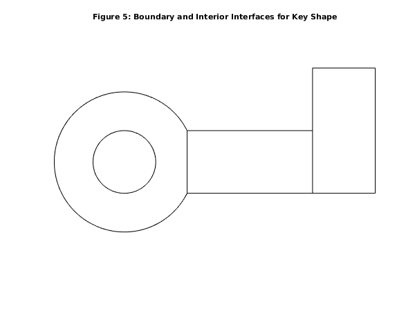
Open in the MATLAB editor: d06db_example
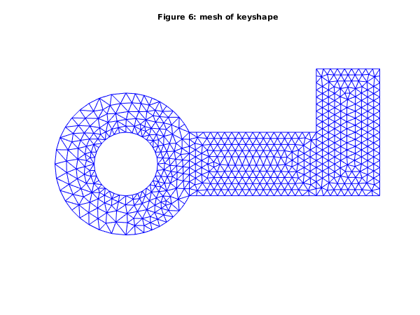
function d06db_example


fprintf('d06db example results\n\n');

d06db_ex1;
d06db_ex2;


function d06db_ex1

  fprintf('Example 1\n\n');
  n = 20;
  coor1 = zeros(2,n^2);
  dx = [0:1/(n-1):1];
  for j = 1:n
    coor1(1,(j-1)*n+1:j*n) = dx;
    coor1(2,(j-1)*n+1:j*n) = dx(j);
  end
  edge1 = ones(3, 4*n-4, 'int64');
  ind = int64(1:n-1);
  edge1(1, 1:(4*n-4)) = [ind,n*ind,n^2+1-ind,n^2+1-n*ind];
  edge1(2, 1:(4*n-5)) = edge1(1, 2:(4*n-4));
  edge1(2, 4*n-4)     = edge1(1, 1);
  conn1 = zeros(3, 2*(n-1)^2, 'int64');

  k = 0;
  l = int64(0);
  for i=1:n-1
    for j=1:n-1
       l = l + 1;
       k = k + 1;
       conn1(1, k) = l;
       conn1(2, k) = l + 1;
       conn1(3, k) = l + n + 1;
       k = k + 1;
       conn1(1, k) = l;
       conn1(2, k) = l + n + 1;
       conn1(3, k) = l + n;
    end
    l = l + 1;
  end
  reft1 = ones(2*(n-1)^2, 1, 'int64');
  reft2 = reft1;
  reft2(:) = int64(2);
  itype = [int64(1)];
  itrace = int64(1);

  for ktrans = 1:2
    if ktrans==2
      % Transform the first domain to obtain an overlapping second domain
      a = (n-5)/(n-1);
      b = (n-3)/(n-1);
      trans = [a; b; 0; 0; 0; 0];
      % plot boundary for partitioned geometry
      fig3 = figure;
      plot([0 1  1 0 0], [0 0 1 1 0], 'black', ...
           [a a+1 a+1 a a],[b b b+1 b+1 b],'black')
      axis off
      axis equal
      title('Figure 3: Boundary of overlapping squares');
      fig4 = figure;
    else
      % Domains partition
      trans = [1; 0; 0; 0; 0; 0];
      % plot boundary for partitioned geometry
      fig1 = figure;
      plot([0 2  2 0 0],[0 0 1 1 0],'black',[1 1],[0, 1],'black')
      axis off
      axis equal
      title('Figure 1: Boundary of partitioned squares');
      fig2 = figure;
    end
    [coor1, edge1, conn1, coor2, edge2, conn2, ifail] = ...
    d06da( ...
           itype, trans, coor1, edge1, conn1, itrace);

    % Restitch the meshes
    [nv3, nelt3, nedge3, coor3, edge3, conn3, reft3, ifail] = ...
    d06db( ...
           coor1, edge1, conn1, reft1, coor2, edge2, conn2, reft2, itrace);

    % Plot the result
    triplot(transpose(double(conn3(:,1:nelt3))), coor3(1,:), coor3(2,:));
    axis equal;
    axis off;
    if ktrans==2
      title ('Figure 4: mesh for two overlapping squares');
    else
      title ('Figure 2: mesh for two partitioned squares');
    end

  end
function d06db_ex2

  fprintf('\n\nExample 2\n\n');

  % First Geometry
  % -----------------------------------------------------------
  nlines = 9;
  % Characteristic points of the boundary mesh
  coorch = [ 2   2   1  -1  -2.2361   0.0000   0   0   0.0000;
            -1   1   0   0   0.0000  -2.2361  -1   1   2.2361];
  % Lines of the boundary mesh
  n10 = int64(10);
  line = [n10 10 10 10 10 10 10 10 10;
            1  2  9  5  6  3  8  4  7;
            2  9  5  6  1  8  4  7  3;
            0  2  2  2  2  1  1  1  1];
  rate = ones(nlines,1);
  % number of connected components
  ncomp = 2;
  nlcomp = int64([5; -4]);
  lcomp = ones(nlines,1,'int64');
  lcomp(1:nlcomp(1))        = [1   2   3   4   5];
  lcomp(nlcomp(1)+1:nlines) = [9   8   7   6];

  % Generate boundary mesh
  nvmax = int64(700);
  nedmx = int64(200);
  itrace = int64(0);
  crus = [0; 0];
  [nvb1, coor1, nedge1, edge1, user, ifail] = ...
  d06ba( ...
         coorch, line, @fbnd, crus, rate, nlcomp, lcomp, nvmax, ...
         nedmx, itrace);

  % Generate mesh using Delaunay-Voronoi method
  weight = [];
  npropa = int64(1);
  [nv1, nelt1, coor1, conn1, ifail] = ...
  d06ab( ...
         nvb1, edge1, coor1, weight, npropa, itrace, 'nedge', nedge1);

  % Smooth
  numfix = int64([0]);
  nqint = int64(0);
  [coor1, ifail] = d06ca( ...
                          coor1, edge1, conn1, numfix, itrace, nqint, ...
                          'nv', nv1, 'nelt', nelt1, 'nedge', nedge1, ...
                          'nvfix', int64(0));

  % Second Geometry
  % -----------------------------------------------------------
  nlines = 4;
  % Characteristic points of the boundary mesh
  coorch = [ 2   6   6   2;
            -1  -1   1   1];
  % Lines of the boundary mesh
  n19 = int64(19);
  line = [n19 10 19 10;
            1  2  3  4;
            2  3  4  1;
            0  0  0  0];
  rate = ones(nlines,1);
  % number of connected components
  ncomp = 1;
  nlcomp = [int64(4)];
  lcomp = int64([1   2   3   4]);

  % Generate boundary mesh
  [nvb2, coor2, nedge2, edge2, user, ifail] = ...
  d06ba( ...
         coorch, line, @fbnd, crus, rate, nlcomp, lcomp, nvmax, ...
         nedmx, itrace);
  % Generate mesh using Advancing Front method
  [nv2, nelt2, coor2, conn2, ifail] = ...
  d06ac( ...
         nvb2, edge2, coor2, weight, itrace, 'nedge', nedge2);

  % Third Geometry (rotation and translation of second)
  % -----------------------------------------------------------
  itype = [int64(3)];
  trans = [6; -1; -90; 0; 0; 0];
  [coor3, edge3, conn3, coor3, edge3, conn3, ifail] = ...
  d06da( ...
         itype, trans, coor2, edge2, conn2, itrace, 'nv', nv2, ...
         'nelt', nelt2, 'nedge', nedge2);

  % -----------------------------------------------------------
  % Combine 3 meshes
  % -----------------------------------------------------------
  % Restitch 1 and 2 to form mesh 4
  reft1(1:nelt1) = int64(1);
  reft2(1:nelt2) = int64(2);
  [nv4, nelt4, nedge4, coor4, edge4, conn4, reft4, ifail] = ...
  d06db( ...
         coor1, edge1, conn1, reft1, coor2, edge2, conn2, reft2, itrace, ...
         'nv1', nv1, 'nelt1', nelt1, 'nedge1', nedge1, ...
         'nv2', nv2, 'nelt2', nelt2, 'nedge2', nedge2);

  % Restitch 3 and 4 to form mesh 5
  reft3(1:nelt2) = int64(3);
  [nv5, nelt5, nedge5, coor5, edge5, conn5, reft5, ifail] = ...
  d06db( ...
         coor4, edge4, conn4, reft4, coor3, edge3, conn3, reft3, itrace, ...
         'nv1', nv4, 'nelt1', nelt4, 'nedge1', nedge4, ...
         'nv2', nv2, 'nelt2', nelt2, 'nedge2', nedge2);

  fprintf(' The restitched mesh characteristics\n');
  fprintf(' nv    = %5d\n', nv5);
  fprintf(' nelt  = %5d\n', nelt5);
  fprintf(' nedge = %5d\n', nedge5);

  % Plot boundary
  fig5 = figure;
  a = asin(1/sqrt(5));
  t1 = linspace(a, 2*pi-a, 100);
  t2 = linspace(0, 2*pi, 100);
  hold on
  r = sqrt(5);
  plot(r*cos(t1),r*sin(t1),'black');
  r = 1;
  plot(r*cos(t2),r*sin(t2),'black');
  plot([2 6 6 2 2],[-1 -1 1 1 -1],'black');
  plot([6 8 8 6 6],[-1 -1 3 3 -1],'black');
  axis off
  axis equal
  title('Figure 5: Boundary and Interior Interfaces for Key Shape');

  % Plot mesh
  fig6 = figure;
  triplot(transpose(double(conn5(:,1:nelt5))), coor5(1,:), coor5(2,:));
  axis equal;
  axis off;
  title ('Figure 6: mesh of keyshape');
function [result, user] = fbnd(i, x, y, user)
  result = 0;
  if (i == 1)
    % inner circle
    result = x^2 + y^2 - 1;
  elseif (i == 2)
    % outer circle
    result = x^2 + y^2 - 5;
  end
d06db example results

Example 1


 Transformation   1: translation
  translation vector:   1.000       0.000

 Final transformation matrix y = A*x + b:
    1.000       0.000          1.000
    0.000       1.000          0.000

 Transformation   1: translation
  translation vector:  0.7895      0.8947

 Final transformation matrix y = A*x + b:
    1.000       0.000         0.7895
    0.000       1.000         0.8947


Example 2

 The restitched mesh characteristics
 nv    =   643
 nelt  =  1133
 nedge =   171